SAP Split Case Pump
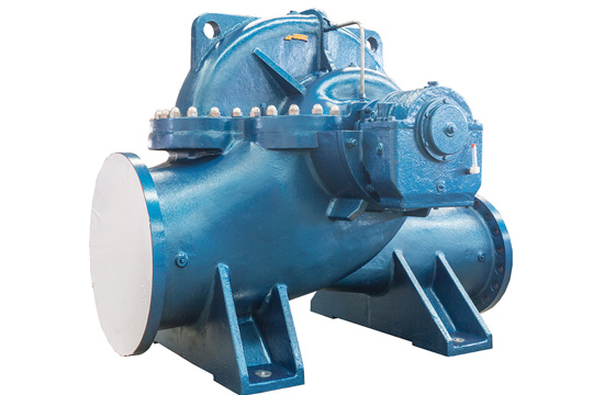
SAP Split Case Pump Description
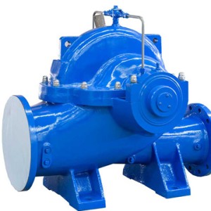
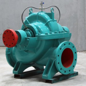
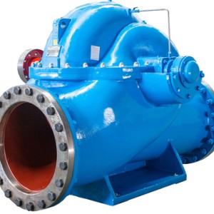
SAP pump is a single-stage double-suction split case centrifugal pump. It is a new product developing from SA-pump on the basis of structural optimal design. The products reserve the characteristics of SA type pump of good hydraulic performance, high efficiency, as well as made a new improvement in structure comprehending the technology of West German KSB company and double-suction pump of United States IR company, make it more reasonable and reliable.
This group transfer branch water containing solid particle and liquid physics chemical properties similar to water, transferred media temperature are 0℃~80℃, suitable factory, urban, mining, power generation, water resources engineering, drainage or water supply pump.
|
Item |
Pump Supporting Program A |
Pump Supporting Program B |
Pump Supporting Program C |
|
|
1 |
2 |
|||
|
Pump casing |
Grey cast iron |
Ductile cast iron |
Ductile cast iron |
Extra low carbon stainless steel |
|
Impeller |
Grey casting iron |
Cast steel |
Stainless steel |
Duplex S.S |
|
Shaft |
#45 steel |
#45 steel |
Stainless steel |
Duplex S.S |
|
Shaft sleeve |
#45 steel |
#45 steel |
Stainless steel |
Extra low carbon stainless steel |
|
Wear ring |
Grey casting iron |
Cast steel |
Cast steel |
Duplex S.S |
|
Services |
For pure water and lower Strength applications |
For pure water high strength applications |
For media with more solid impurities,PH<6 Chemical corrosion and for high strength applications |
|
|
These configurations are recommended by the manufacturer,customers could change materials according to specific needs. |
||||
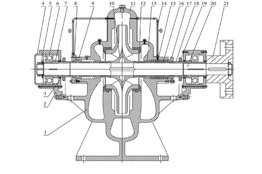
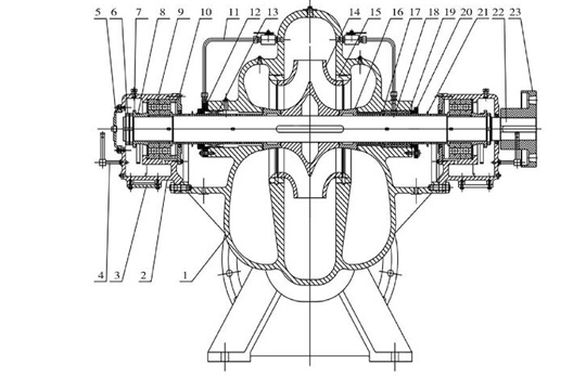
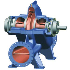
SAP Split Case Pump Structure Feature
The shaft seal is soft packing or mechanical seal, the packing ring is installed before packing in order to prevent air from entering pump, cooling and lubricating seal chamber. While the pump operation, a small amount of high pressure water flow into the packing or mechanical seals chamber through the ladder-shaped groove on the horizontally split face of the pump cover, which function as water seal.
Main Parts of pump: Lower Casing; Upper Casing; Impeller; Shaft; Double Suction Seal Ring; Shaft Sleeve.……etc…
1, The impeller working chamber consists of pump body and the pump cover. The spiral holes for installing the vacuum gauge and pressure gauge locate at the inlet flange and the outlet flange .At the bottom of the inlet and outlet flange have drain spiral hole.(According to customer requirements using stainless steel shaft and bronze impeller)
2, The double suction seal ring is used to reduce water leakage from the pump pressure chamber flow back to the suction chamber.
1, The inlet and outlet of this type pump both below the pump axis, they are vertical to axis and in horizontal orientation. Maintain without needing to remove inlet, outlet of pipes and electric motor. Looking from driving directions SAP-type pumps are counter clockwise direction.(According to user needs can also be changed to clockwise)
3, In addition to shafts are made of quality carbon steel, the remaining main parts are made of cast iron.
4, The pump shaft is supported by single row radial ball bearings. The bearing is installed at the bearing body which fitted on both ends of the pump casing.
5, The impeller adjusted by static balancing is fixed on the shaft by the shaft sleeves and the nuts。For the axial force of the impeller, it can be balanced by symmetrical distribution of the impeller and the both sides intake water .
6, The pump is driven by the motor through the flexible coupling.(It also can be driven by diesel engine if necessary)
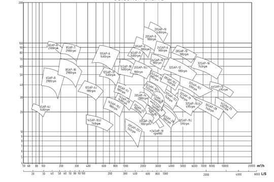
SAP Split Case Pump Technical Data
|
Type |
Capacity |
Head |
Speed |
Shaft power |
Motor power |
EFF |
(NPSH)r |
The structural form |
||
|
(m3/h) |
(l/s) |
(m) |
(r/min) |
(kw) |
(kw) |
(%) |
(m) |
|||
|
6SAP-6 |
|
126 180 216 |
35 50 60 |
104 97 87 |
2980 |
48.8 59.4 64.7 |
75 |
73 80 79 |
3.0 3.8 5.3 |
Structure drawing I |
|
A |
119 170 204 |
33 47.2 56.6 |
91 84.5 76 |
2980 |
42 50.1 54.7 |
75 |
70 78 77 |
3.0 3.7 4.7 |
||
|
J |
72 90 108 |
20 25 30 |
25 22.5 20 |
1480 |
6.7 7.4 8.4 |
11 |
73 74 70 |
2.6 2.7 2.9 |
||
|
6SAP-8 |
|
108 160 193 |
30 44.5 53.5 |
58 54 50 |
2980 |
24.3 29 31.2 |
37 |
70 81 84 |
2.9 3.8 4.4 |
|
|
A |
108 144 174 |
30 40 48.3 |
46 44 39 |
2980
|
17.8 21.5 23 |
30 |
76 80 80 |
2.9 3.6 4.1 |
||
|
B |
108 133 160 |
30 36.9 44.5 |
38 36 32 |
2980 |
15.5 16.9 18.1 |
22 |
72 77 77 |
2.9 3.4 3.8 |
||
|
8SAP-7 |
|
216 280 336 |
60 77.8 93.5 |
99 95 87 |
2980 |
78.6 90.5 100.9 |
132 |
74 80 79 |
4.0 4.7 6.0 |
|
|
A |
210 262 314 |
58.4 72.8 87.2 |
87 83 74 |
2980 |
68.2 76.9 83.2 |
110 |
73 77 76 |
4.0 4.5 5.7 |
||
|
B |
196 247 300 |
54.4 68.6 83.4 |
76 73 63 |
2980 |
56.2 64.6 71.5 |
75 |
72 76 72 |
4.0 4.2 5.4 |
||
|
8SAP-10 |
|
194 280 351 |
53.9 77.8 97.5 |
71 63 52 |
2980 |
52.1 59.3 65.4 |
75 |
72 81 76 |
2.8 4.1 5.3 |
|
|
A |
180 259 324 |
50 72 90 |
58 52 41 |
2980 |
40.6 46.4 50.2 |
55 |
70 79 72 |
2.7 3.8 4.9 |
||
|
B |
173 239 288 |
48 66.4 80 |
48 44 36 |
2980 |
32.2 36.7 38.1 |
45 |
70 78 74 |
26 3.5 4.2 |
||
|
10SAP-6 |
|
432 540 720 |
120 150 200 |
96 94 89 |
1480 |
152.6 177.2 215.4 |
250 |
74 78 81 |
5.1 6.3 9.2 |
|
|
A |
432 540 720 |
120 150 200 |
85.3 84 76 |
1480 |
129.3 154.4 186.2 |
220 |
77.6 80 80 |
5.1 6.3 9.2 |
||
|
B |
432 540 720 |
120 150 200 |
76.4 74 67 |
1480
|
121.4 137.7 164.2 |
185 |
74 79 80 |
5.1 6.3 9.2 |
||
|
Type |
Capacity |
Head |
Speed |
Shaft power |
Motor power |
EFF |
(NPSH)r |
The structural form |
||
|
(m3/h) |
(l/s) |
(m) |
(r/min) |
(kw) |
(kw) |
(%) |
(m) |
|||
|
10SAP-6 |
C |
400 500 600 |
111.1 138.9 166.6 |
66.4 65.6 62.5 |
1480
|
95.1 113 130.8 |
160 |
76 79 78 |
4.6 5.7 7.5 |
Structure drawing I |
|
J |
400 500 600 |
111.1 138.9 166.7 |
42 39 35 |
980 |
58.6 65.5 72.4 |
90 |
78 81 79 |
3.6 4.7 6.6 |
||
|
JA |
300 400 500 |
83.3 111.1 138.9 |
36.8 36 33 |
980 |
39.3 49.6 56.1 |
75 |
76.4 79 80 |
3.3 3.6 4.7 |
||
|
JB |
300 400 500 |
83.3 111.1 138.9 |
33 32 28 |
980 |
34.7 44.1 48.2 |
55 |
77.5 79 79 |
3.3 3.6 4.7 |
||
|
12SAP-10 |
|
610 790 900 |
169.4 219.4 250 |
59 54 47.8 |
1480 |
113.9 131.9 137.8 |
160 |
86 88 85 |
4.1 4.6 5.1 |
|
|
A |
570 740 846 |
158.3 205.6 235 |
52 47.5 42 |
1480 |
93.8 108.9 113.9 |
132 |
86 87.9 84.9 |
4.0 4.4 4.8 |
||
|
B |
530 686 780 |
147.2 190.6 216.7 |
147.2 190.6 216.7 |
1480 |
73.9 85.9 98.9 |
110 |
86.5 88 85 |
3.9 4.3 4.6 |
||
|
14SAP-10 |
|
900 1080 1260 |
250 300 350 |
70 68 64 |
1480 |
206.7 229.8 249.5 |
280 |
83 87 88 |
5.0 6.3 6.9 |
|
|
A |
900 1080 1260 |
250 300 350 |
60 58 54 |
1480 |
175 196 212.9 |
250 |
84 87 87 |
5.1 6.3 6.9 |
||
|
B |
900 1080 1260 |
250 300 350 |
51 48 44 |
1480 |
148.8 162.2 179.7 |
220 |
84 87 84 |
5.1 6.3 6.9 |
||
|
J |
650 800 1000 |
180.6 222.2 277.8 |
30 28 24 |
980
|
162.4 70.1 77.8 |
90 |
85 87 84 |
4.0 4.1 5.1 |
||
|
JA |
600 720 900 |
166.7 200 250 |
27 25 22 |
980 |
52.5 56.3 62.6 |
75 |
84 87 86 |
4.0 4.8 4.1 |
||
|
JB |
600 720 900 |
166.7 200 250 |
23 21 18 |
980 |
44.2 47.3 51.9 |
75 |
85 87 85 |
4.0 4.0 4.1 |
||
|
JJA |
450 547 684 |
125 151.9 190 |
15.6 14.5 12.7 |
740
|
22.7 25.1 27.8 |
37 |
84 86 85 |
5.8 5.8 5.8 |
||
|
14SAP-20 |
|
870 1320 1550 |
241.7 366.7 430.6 |
33 26 21.5 |
1480 |
101.5 109.9 111.3 |
132 |
77 85 81.5 |
5.8 7.8 10.1 |
|
|
16SAP-9 |
|
1080 1260 1620 |
300 350 450 |
97.6 96 90 |
1480 |
400.9 427.8 472.6 |
630
|
71.6 77 84 |
5.5 7.0 8.5 |
Structure drawing II |
|
A |
1080 1260 1620 |
300 350 450 |
85.5 85 78 |
1480 |
344.4 394.1 409.6 |
450 |
73 74 84 |
5.2 5.9 7.9 |
||
|
Type |
Capacity |
Head |
Speed |
Shaft power |
Motor power |
EFF |
(NPSH)r |
The structural form |
||
|
(m3/h) |
(l/s) |
(m) |
(r/min) |
(kw) |
(kw) |
(%) |
(m) |
|||
|
16SAP-9 |
B |
1080 1260 1620 |
300 350 450 |
78 76 68 |
1480 |
297.9 318 348.8 |
450 |
77 82 86 |
5.2 5.9 7.9 |
Structure drawing II |
|
J |
900 1080 1260 |
250 300 350 |
42 40 37 |
980 |
128.6 140 149.3 |
185 |
80 84 85 |
4.6 4.9 5.2 |
||
|
JA |
900 1080 1260 |
250 300 350 |
37 35 32 |
980 |
111.9 122.5 130.7 |
160 |
80 83 86 |
4.6 4.9 5.2 |
||
|
JB |
800 900 1080 |
222 250 300 |
33 32 30 |
980 |
89.8 94.4 102.5 |
132 |
72.8 78.4 82.3 |
4.6 4.6 4.6 |
||
|
20SAP-5 |
|
1667 2000 2400 |
463.1 555.6 666.7 |
130.4 127.5 120.6 |
980 |
813.2 885.8 957.8 |
1120 |
72.8 78.4 82.3 |
4 4.8 5 |
Structure drawing I |
|
A |
1500 1875 2250 |
416.67 521 625 |
113.3 109 103.4 |
980 |
648.2 709.2 770.7 |
800 |
71.4 78.5 82.2 |
4 4.8 5 |
||
|
B |
1408 1760 2112 |
391.1 489 586.67 |
101 96.8 91.4 |
980 |
545.4 594.9 641.1 |
710 |
71 78 82 |
2.6 3.2 3.4 |
||
|
20SAP-6 |
|
1500 2160 2500 |
416.1 600 694.4 |
112 100 87.5 |
980 |
571.1 700.2 739.9 |
800 |
80 84 80.5 |
3.4 4.6 5.6 |
|
|
|
A |
1414 2036 2357 |
392.8 656.6 654.7 |
101 88.9 77.8 |
980 |
479 583.3 616.5 |
710 |
80 84.5 81 |
3.4 4.4 5.2 |
|
|
|
B |
1320 1900 2200 |
367 528 611 |
88.6 77.4 66 |
980 |
400.9 476.9 497.2 |
560 |
79.5 84 79.5 |
3.4 4.1 4.8 |
|
|
20SAP-10 |
|
1500 2160 2500 |
416.7 600 694.4 |
65.5 60 55.5 |
980 |
338.7 401 434.2 |
500 |
79 88 87 |
6.6 |
|
|
|
A |
1410 2034 2355 |
391.6 565 654 |
58 53.2 49.3 |
980 |
281.8 338.7 367.5 |
400 |
79 87 86 |
6.6 |
|
|
|
B |
1326 1910 2210 |
368 531 614 |
51.2 47 43.4 |
980 |
232.3 287.8 307.3 |
355 |
79.5 85 85 |
6.6 |
|
|
20SAP-10-A |
|
2160 3384 4320 |
600 940 1200 |
600 940 1200 |
1480 |
1161.1 1413.7 1606.8 |
1600 |
77 88 82 |
6.6 |
|
|
|
A |
2160 3384 4320 |
600 940 1200 |
133 116 93 |
1480 |
1003 1228.7 1367.6 |
1400
|
78 87 80 |
6.6 |
|
|
|
B |
2160 3384 4320 |
600 940 1200 |
115 98 72 |
1480 |
856.2 1088.1 1114.5 |
1120 |
79 83 76 |
6.6 |
|
Related products
-
XS Split Case Pump
Outlet diameter: 80~900mm
Capacity: 22~16236m3/h
Head: 7~300m
Solid parameter: ≤80mg/L
Permissible pressure: ≤5Mpa -
SDS Multistage Split Case Pump
Outlet diameter: 50-500mm
Capacity: 25-1900m3/h
Head: 60-1100m
Solid Parameter: ≤80mg/L
Temperature T: -20℃-200℃
-
OS Split Case Pump
Flow: 110m3/h-12500m3/h
Lift: 10m-220m
Caliber: 80-800mm
Power: 7.5kw-2000kw
Temperate: ≤105℃ -
MS Split Case Pump
Outlet diameter: 100~1200mm
Capacity: 70~22392m3/h
Head: 8~150m
Temperature: -20℃~200℃
Permissible pressure: ≤4Mpa