1. Water pump flow calculation formula:
What is the pump flow calculation formula? In the process of pump use, it is often necessary to calculate the pump flow, but many people don’t know much about the pump flow calculation formula. Let’s take submersible pumps and gear pumps as examples to introduce the pump flow calculation formula in detail.
The volume of the liquid discharged by the pump per unit time is called the flow rate, and the flow rate is expressed by Q. The unit of measurement: cubic meter/hour (m3/h), liter/second (l/s), L/s=3.6 m3/h=0.06 m3/ min=60L/minG=Qρ G is the weight and ρ is the specific gravity of the liquid.
The shaft power of the pump (kw) = water delivery (l/sec) × head (m) / 102 × efficiency = flow × head × density × acceleration of gravity. 102 is the unit finishing constant.
Water pump effective power / water pump shaft power = pump efficiency (generally 50%-90%, larger pumps are higher)
The energy obtained by the unit weight of the liquid through the pump is called the head. The head of the pump, including the suction, is approximately equal to the pressure difference between the outlet and the inlet of the pump. The head is represented by H, and the unit is meter (m).
The efficiency of a pump refers to the ratio of the effective power of the pump to the shaft power. η=Pe/P The power of a pump usually refers to the input power, that is, the power transmitted from the prime mover to the pump shaft, so it is also called shaft power, which is represented by P. The effective power is: the product of the pump’s head, mass flow and gravitational acceleration.
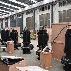
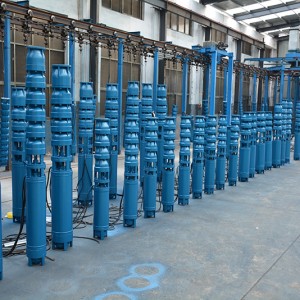
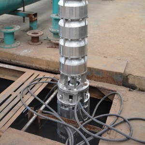
Formula for calculating flow of submersible pump:
60HZ flow×0.83=50HZ flow
60HZ head×0.69=50HZ head
60HZ power ÷ 1.728=50HZ motor power
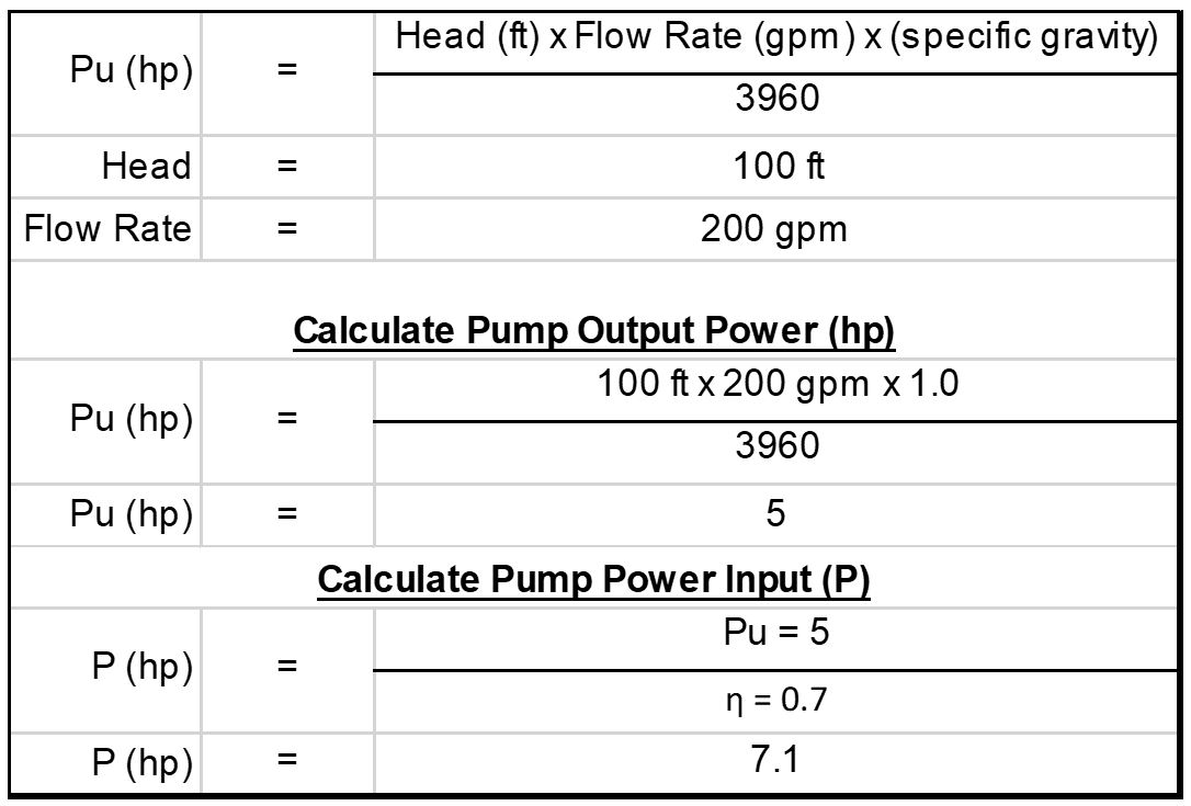
Motor output power = Q (flow) × H (head) / 367.2 / efficiency × 1.15
Motor output power = shaft power × 1.15
Pump efficiency=Q×H×0.00272/motor power
Q means flow; H means head; 0.83/ 0.69/ 1.728/ 367.2/ 1.15/ 0.00272, etc. are all coefficients
The formula for calculating the flow rate of the gear oil pump is:
Q=2qZnηv
Where Z is the number of teeth;
n——revolution, revolution/min;
ηv-volumetric efficiency, for general gear oil pumps, its value can be set to 0.70~0.90;
q——The volume of the pit between the two teeth, cubic meters.
2. Calculation formula of pump head:
Estimate method 1:
Selection of HVAC pumps: usually choose a centrifugal clean water pump with a specific speed of ns between 130 and 150. The flow of the pump should be 1.1 to 1.2 times the rated flow of the chiller (1.1 for a single unit and 1.2 for two units in parallel. According to estimation The loss along the way per 100 meters of pipe length can be roughly taken as 5mH2O, and the pump head (mH2O):
Hmax=△P1+△P2+0.05L (1+K)
△P1 is the water pressure drop of the evaporator of the chiller.
△P2 is the water pressure drop of each unit in the loop that accounts for the largest water pressure loss of the air conditioner’s end device.
L is the length of the most unfavorable loop
K is the ratio of the sum of the equivalent lengths of local resistance in the most unfavorable loop to the total length of the straight pipe. When the most unfavorable loop is longer, the value of K is 0.2~ 0.3, and when the most unfavorable loop is short, the value of K is 0.4~0.6.
Estimate method 2:
What we are talking about here is the resistance composition of the closed air conditioning cold water system, because this system is a commonly used system.
1. Chiller resistance: provided by the unit manufacturer, generally 60~100kPa.
2. Pipeline resistance: including frictional resistance and local resistance. The frictional resistance per unit length, that is, the biscuit group, depends on the comparison of technology and economy. If the value is large, the pipe diameter will be small and the initial investment will be saved, but the energy consumption of the pump operation will be large; if the value is small, the opposite is true. In the current design, the biscuit group of the cold water pipeline should be controlled within the range of 150~200Pa/m. When the pipe diameter is larger, the value can be smaller.
3. The resistance of the air conditioner’s end device: the types of end devices include fan-coil units, combined air conditioners, etc. Their resistance is provided by the manufacturer after calculating the coil configuration according to the parameters of the air entering and exiting the air conditioning coil, the cooling capacity, and the water temperature difference proposed by the design. Many rated operating conditions can be found on the product samples. This resistance is generally in the range of 20~50kPa.
4. The resistance of the regulating valve: air-conditioned rooms always require room temperature control. The installation of an electric two-way regulating valve on the waterway of the air-conditioning terminal device is a means to achieve room temperature control. The size of the two-way valve is selected by the flow capacity and allowable pressure drop when the valve is fully open. If the allowable pressure drop is large, the control performance of the valve is good; if the value is small, the control performance is poor. The percentage of the pressure drop when the valve is fully open to the total pressure drop of the branch is called the valve authority. The water system design requires the valve authority S>0.3, so the allowable pressure drop of the two-way control valve is generally not less than 40kPa.
Based on the above, the pressure loss of the air-conditioning water system of a high-rise building about 100m high can be roughly estimated, that is, the required head of the circulating water pump:
1. Chiller resistance: take 80 kPa (8m water column);
2. Pipeline resistance: take the resistance of the decontamination device, water collector, water separator and pipeline in the refrigerating machine room to 50 kPa; take the pipeline length of the transmission and distribution side 300m and the specific friction 200 Pa/m, then The friction resistance is 300*200=60000 Pa=60 kPa; if the local resistance on the transmission and distribution side is considered to be 50% of the friction resistance, the local resistance is 60 kPa*0.5=30 kPa; the total resistance of the system pipeline is 50 kPa+ 60 kPa+30 kPa=140 kPa (14m water column);
3. The resistance of the air conditioner terminal device: the resistance of the combined air conditioner is generally greater than the resistance of the fan coil, so the resistance of the former is 45 kPa (4.5 water column);
4. The resistance of the two-way regulating valve: take 40 kPa (0.4 water column).
5. Therefore, the sum of the resistance of each part of the water system is: 80 kPa+140kPa+45 kPa+40 kPa=305 kPa (30.5m water column)
6. Water pump head: take 10% safety factor, then head H=30.5m*1.1=33.55m.
According to the above estimation results, the pressure loss value range of the air conditioning water system of buildings of the same size can be basically grasped. In particular, it is necessary to prevent the system pressure loss from being too conservative and the system pressure loss estimated to be too large and the pump head selected to be too large because it has not been calculated. Lead to waste of energy.
Post time: 2021-12-30