Parallel operation of water pumps, on the one hand, can increase the flow of the system, on the other hand, the flow of the system can be adjusted by the number of openings, so it is widely used. However, for a certain piping system, if the pump type is improperly selected, there may be two (or more) parallel operation compared with single operation, the flow increase is small. For example [1]: 200RXL-24 water pump works in a system with a pipeline characteristic curve of H = 4.48×10⁻⁴G2mH2O. When a single unit is running, the flow rate is 236.4 m3/h; when two units are running in parallel, the flow rate is 246.7 m3/h; When three units are operated in parallel, the flow rate is 250.6 m3/h. Obviously, in this case, parallel connection is meaningless, because it is neither possible to increase the flow rate by parallel connection, nor to effectively adjust the flow rate by changing the number of operating units. Furthermore, because the pumps are selected according to the parallel working conditions, the single machine working conditions in parallel operation are in a reasonable working area, and the flow rate of a single machine in operation will be much larger than that of a single machine in parallel operation, which seriously deviates from the reasonable working area. , The efficiency is reduced, the required power is greatly increased, and the motor may be overloaded. Therefore, it is necessary to understand the factors related to the increase in flow rate in parallel operation compared with single operation, which is necessary for correct pump selection and system design. For the convenience of description, for two parallel operation (this article only discusses two parallel operation), compared with single operation, the increase in flow is called the flow increase of parallel operation in this article, and is expressed by ΔG.
2. The influence of pump characteristics on ΔG
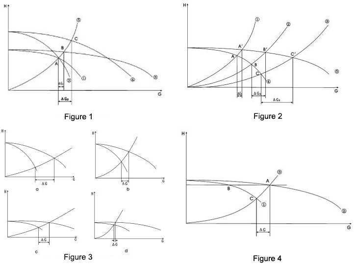
As shown in Figure 1, the characteristic curve of pump 1 is ①, which is relatively flat; the characteristic curve of pump 2 is ②, which is steep; they have an intersection A. For the convenience of comparison, suppose that the pipeline characteristic curve ⑤ just passes point A, that is to say, when pump 1 and pump 2 are working in this system respectively, the working conditions are both A. The characteristic curve of two pumps 1 in parallel is ③, and the characteristic curve of two pumps in parallel is ④, and their intersections with the pipeline characteristic curve ⑤ are B and C respectively. Obviously, the parallel flow increment ΔG 2 of pump 2 is greater than the parallel flow increment ΔG1 of pump 2. This shows that the steeper the characteristic curve of the pump (the larger the specific speed) and the larger the ΔG, the more suitable for parallel operation. Conversely, the flatter the characteristic curve of the pump (the smaller the specific speed) and the smaller the ΔG, the less suitable for parallel operation.
3. The influence of pipeline impedance on ΔG
As shown in Figure 2, ①, ②, and ③ are three pipeline characteristic curves, namely H=S1G2, H=S2G2, H=S3G2, and pipeline impedance S1>S2>S3. ④ is the characteristic curve of the pump, ⑤ is the characteristic curve of two parallel connection. When a single pump works in three systems, the operating points are A, B, and C; when two parallel pumps work in three systems, the operating points are A’, B’, and C’. Obviously, ΔG1<ΔG2<ΔG3, that is, the larger the pipeline impedance S, the smaller the parallel flow increment ΔG; conversely, the smaller the S, the larger the ΔG. In other words, reducing the impedance of the piping system can increase the flow increase of the parallel pumps. The smaller the pipeline impedance (the flatter the characteristic curve), the more suitable for the parallel operation of water pumps. The greater the pipeline impedance (the steeper the characteristic curve), the less suitable for parallel operation of pumps.
4. The comprehensive influence of pump characteristics and pipeline impedance on ΔG
From the above analysis, it can be seen that the flow increment ΔG of the parallel operation of water pumps is not only related to the characteristics of the pump, but also related to the impedance of the piping system. Then, if you simply divide the pump characteristic curve into flat type and steep drop type, and divide the pipeline characteristic curve into slow rise type and steep rise type, they can have four combinations as shown in Figure 3. Obviously, the combination of the steep drop type of the pump curve and the slow rise type of the pipeline curve gives a larger ΔG (Figure 3a); the combination of the flat type of the pump curve and the steep rise type of the pipeline curve (Figure 3d) makes the ΔG smaller; other For the two combinations, ΔG is in the middle.
Of course, “flat”, “steep” and “slow” are all vague terms, and there is no quantitative definition, but these qualitative conclusions can at least make it clear what direction to work hard to increase the parallel flow increment of the pumps.
5. The possible overload problem and ΔG that may occur when the number of open units is used for adjustment
Regarding the parallel operation of two or more pumps, both designers and users have the awareness: According to the size of the load, change the number of pumps to open, that is, open more when the load is large, and open less when the load is small. It should be said that this is also an important reason for using parallel connection. However, if the parallel flow increment ΔG of the pumps is too small, changing the number of open units may cause the pump motor to overload. As shown in Figure 4, the parallel operation condition is A, the single unit operation condition in parallel operation is B, and the single unit operation condition is C. Obviously, the flow rate GC during single operation is greater than the flow rate GB during parallel operation. The smaller the ΔG (=GA-GC), the larger the GC. In addition, the parallel operating condition is a design operating condition, and the single unit operating condition B during parallel operation should be in a reasonable working area (a region with higher efficiency), while the single operating condition C often deviates from the reasonable operating area and the efficiency is reduced. The smaller the ΔG, the farther C and B are, and the greater the efficiency difference between the two working conditions. Therefore, if the ΔG is too small, the shaft power of the C working condition will greatly exceed the B working condition, and overloading may occur when a single unit is running. Here is an example: using KQL125/300-11/4 type water pump, the recommended flow range is 55-110 m3/h. As shown in Figure 4, two parallel operating conditions A are selected on the parallel characteristic curve ②: 162m3/h, 27 mH2O, then the single-unit operating conditions B in parallel operation are: 81 m3/h, 27 mH2O, Within the recommended traffic area. From the parameters of A working condition, the pipeline characteristic curve can be obtained as H=1.03×10⁻³G2 (considered here as a closed system). Then, the operating condition of a single unit should be the intersection of the pump characteristic curve ① and the pipeline characteristic curve ③, but in fact ① and ③ cannot intersect, and can only be extended along the arc of ①, and the intersection point C with ③, Approximately considered to be a single operating condition. Working condition C is: 151 m3/h, 22 mH2O. Then GC is 86.4% larger than GB, and C working condition is seriously deviated from the recommended working area, and the efficiency must be lower (may be much lower) than B working condition, so the power required for C working condition will greatly exceed B working condition. If the pump motor is configured according to the recommended flow area, it will definitely be overloaded when a single unit is running.
Then GC is 86.4% larger than GB, and C working condition is seriously deviated from the recommended working area, and the efficiency must be lower (may be much lower) than B working condition, so the power required for C working condition will greatly exceed B working condition.
6. Several issues that should be paid attention to in the design and operation of the parallel pump system
⑴. Try not to use pumps whose performance curve is too flat, and pay attention to reducing the system impedance to increase the flow difference ΔG between parallel operation and single operation. In this way, the overload of the pump motor can be avoided, and the number of units can be adjusted to have a better effect.
⑵. When selecting water pumps, you should not only consider the parallel operating conditions, you must check the operating conditions of a single unit, whether the flow can meet the adjustment requirements, and whether there is a possibility of overload.
⑶. For the selection of pumps, parallel operation and single operation should be made as far as possible, and the pumps should work in the high-efficiency area. Of course, this is often difficult to achieve, so it should be optimized according to the time ratio of parallel operation and single operation, so that the operating power consumption of the pump is the least within one year (or one operating cycle).
⑷. For the existing system, if the ΔG is too small, a single unit may be overloaded. The best remedy is to install a self-operated restrictor valve. When a single unit is running, the restrictor valve automatically changes its opening and increases Impedance, reduce the flow rate. A balance valve can also be installed. When a single unit is running, the impedance can be increased manually and the flow can be reduced.
7. Concluding remarks
The size of the flow increment ΔG of the parallel operation of pumps is a problem that must be considered in the selection of the pump and the design of the system for a system that adopts the number of openings for adjustment.
This article only analyzes the situation of two units in parallel. For more than two units in parallel operation, it is not difficult to use the same method to get an approximate conclusion. Obviously, for multiple parallel systems of pumps, it is necessary to pay more attention to the flow, efficiency and overload problems of a single pump during operation.
Post time: 2022-01-06