Centrifugation is actually a manifestation of the inertia of objects. We can often observe the following phenomena in our lives: For example, when the umbrella rotates slowly, the water drops will fly out along the tangent direction of the umbrella edge, and the rotating umbrella gives energy to the water droplets. The centrifugal force of the rotation throws away the water droplets. This is because the friction between the umbrella and the water droplets acts as a centripetal force for the water droplets. But if the umbrella rotates faster, this friction is not enough to make the water droplets move in a circular motion, then the water droplets will move away from the umbrella to the outer edge, just like a rope is used to pull a rock in a circular motion, if the speed is too fast, the rope will move When disconnected, the rocks will fly out. This is called centrifugation. The centrifugal pump is designed according to the above-mentioned principle of centrifugal force water throwing. The high-speed rotating impeller blades of the water pump drive the water to rotate. The outlet pipe achieves the purpose of conveying, which is the working principle of the centrifugal pump.
1. Classification of water pumps
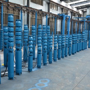
The purpose of a water pump is to transport water from one place to another, or to increase the pressure to convert the mechanical energy of the motive force into liquid energy. According to the working principle, the pumps are divided into three categories: vane pumps, product pumps and other types of pumps. The vane pump transfers energy to the fluid mainly through the rotation of the impeller. Positive displacement pumps are mainly used to periodically change the volume of the working chamber containing the fluid and transfer to the fluid. Among them, the centrifugal pump is a kind of vane pump, and it is also the most widely used pump. This is mainly because the centrifugal pump has a wide range of applicable performance, small size, light weight, low cost, simple structure, convenient operation, and fewer failures. , Long life, no pulsation of discharged liquid, etc.
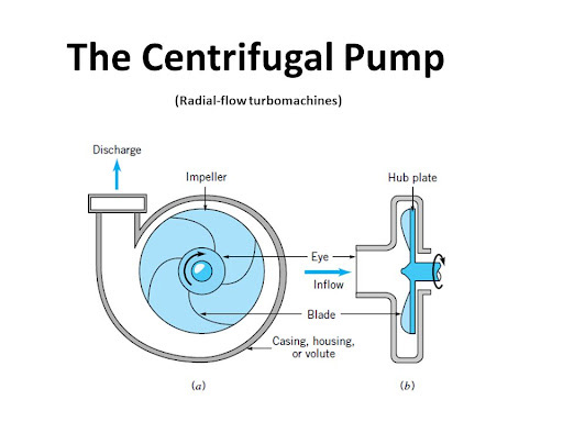
2. Working principle of centrifugal pump
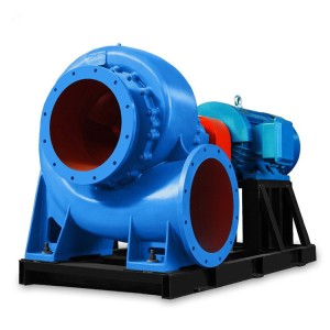
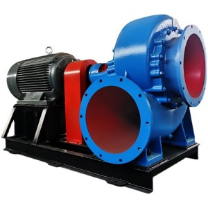
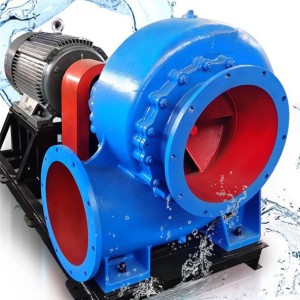
The basic components of a centrifugal pump are a high-speed rotating impeller and a fixed snail-shaped pump casing. An impeller with several (usually 4-12) backward curved blades is fastened to the pump shaft and is driven by a motor to rotate at a high speed along with the pump shaft. The impeller is a component that directly performs work on the liquid in the pump, and is the energy supply device for the centrifugal pump. The suction port in the center of the pump casing is connected with the suction pipe, and the bottom of the suction pipe is equipped with a one-way bottom valve. The discharge port on the side of the pump casing is connected with the discharge pipeline equipped with a regulating valve.
The centrifugal pump is mainly composed of a suction chamber, a discharge pipe, an impeller, and a press-out chamber. When the prime mover drives the impeller to rotate at a high speed through the shaft, the blades on the impeller will force the fluid to rotate, that is, the blades will work on the fluid along the tangential direction of its circumference to increase the pressure and kinetic energy of the fluid. Near the outer edge of the impeller outlet, due to the highest circumferential tangential velocity, the fluid at the location will have the highest pressure energy and kinetic energy. Under the action of inertial centrifugal force and differential pressure force, the fluid will be removed from the outer edge of the impeller outlet, and be transported to the destination through the press-out chamber (volute), discharge pipe, and outlet pipe. At the same time, due to the action of inertial centrifugal force, the fluid is discharged from the impeller outlet, forming a tendency of fluid vacancy in the center of the impeller, that is, a low pressure area is formed in the center of the impeller. Under the action of suction short pressure, the fluid flows from the suction pipe to the center of the impeller through the suction chamber. When the impeller rotates continuously, the fluid is continuously sucked in by the center of the impeller and discharged through the outlet of the outer edge of the impeller, forming the working process of the centrifugal pump to continuously deliver the fluid.
3. Air binding phenomenon of centrifugal pump
When there is air in the pump casing, the density of the air is much lower than that of the liquid, which produces a smaller centrifugal force. Therefore, the pressure difference between the liquid surface of the storage tank and the suction port of the pump is not enough to press the liquid in the storage tank into the pump, that is, the centrifugal pump has no self-priming ability, so that the centrifugal pump cannot deliver the liquid. This phenomenon is called “gas binding”. Phenomenon”. In order to fill the pump with liquid, a bottom valve with a filter screen is usually installed at the bottom of the suction pipe. The bottom valve is a check valve. The filter screen is used to prevent solid matter from entering the pump to damage the impeller or prevent the normal operation of the pump.
4. The basic performance parameters of centrifugal pumps
The performance parameters of the centrifugal pump involve the energy of the fluid. For convenience, the head is often used to measure the amount of fluid energy. The international standard definition of headland is: “the ratio of the energy of a unit mass fluid to the acceleration of gravity”. The potential energy, kinetic energy, and pressure energy of a fluid can all be expressed by a water head.
Position head: The potential energy of a fluid at a height from the reference plane is the mass multiplied by the height and then multiplied by the acceleration of gravity. According to the definition of water head, the potential energy of a unit mass fluid divided by the acceleration of gravity is the position head: velocity head: the kinetic energy of a fluid flowing at a constant speed is the mass divided by the velocity squared divided by 2. The kinetic energy of a unit mass fluid divided by gravity Acceleration is the speed head, the unit is meter: Pressure head: The unit of static pressure of the fluid is Pa, which is the unit of pressure. The energy unit of the fluid is also Pa=J/m3, which refers to the energy per unit volume of the fluid. The energy per unit mass of the fluid should be divided by the density of the fluid, and the value obtained is divided by the acceleration of gravity to obtain the pressure head.
The sum of the position head, velocity head, and pressure head of the fluid becomes the total head. The centrifugal pump has 9 basic properties, such as flow (volume of fluid delivered by the pump per unit time), head (energy obtained by the fluid per unit mass through the pump), shaft power (output power of the prime mover), effective power (pump Transmission to fluid power), efficiency (ratio of pump output power to shaft power), speed (pump shaft rotation speed), required cavitation margin (refers to the cavitation margin required by the pump at a given speed and flow rate) quantity). In addition, the centrifugal pump is allowed to suck up the vacuum height and specific speed.
The cavitation margin of the pump means that when the liquid pressure in a certain area decreases the vaporization pressure of the liquid at the current temperature during the operation of the pump, the liquid begins to vaporize and form bubbles. When these bubbles move forward with the liquid to a higher pressure zone, the bubbles shrink sharply under compression and rupture, resulting in a huge condensation shock that is inwardly explosive. When the bubble burst occurs on the wall of the flow channel between the blades, a fine jet will be generated, which impacts the wall at high speed, forming a local high pressure on the wall (up to tens to hundreds of megapascals), and as a result, an onlooker crack is generated on the wall. , It will cause the wall material to be corroded, and repeated it will destroy the centrifugal pump.
Basic performance parameters of centrifugal pumps
5. General characteristics of centrifugal pumps
(1) The flow direction of water along the centrifugal pump is sucked in along the axial direction of the impeller, and flows out perpendicular to the axial direction, that is, the direction of water flow in and out is 90° with each other.
(2) Since the centrifugal pump relies on the impeller inlet to form a vacuum suction, it is necessary to fill the pump and suction pipe with water before starting, or use a vacuum pump to exhaust air to form a vacuum, and the pump casing and suction pipe must be strictly sealed. There must be no air leakage, otherwise a vacuum will not be formed and water will not be sucked up.
(3) Since it is impossible to form an absolute vacuum at the impeller inlet, the suction height of the centrifugal pump cannot exceed 10 meters. In addition to the loss along the way caused by the water flowing through the suction pipe, the actual allowable installation height (the height of the pump axis from the suction water surface) is much smaller than 10 m. If the installation is too high, the water will not be absorbed; in addition, since the atmospheric pressure is lower in mountainous areas than in plains, the installation height of the same pump in mountainous areas, especially in high mountainous areas, should be lowered, otherwise the water cannot be sucked up.
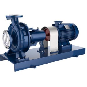
Features: The centrifugal pump has a simple structure, can be directly connected with the motor, is not limited by the speed, is not easy to wear, runs smoothly, has low noise, uniform media discharge, convenient adjustment, high efficiency, and reliable operation. The widest scope of application.
Disadvantages: The sealing performance is poor, and the mechanical seal is easily damaged. Cavitation is more serious, and most centrifugal pumps have no self-priming ability.
6. Classification and structure of centrifugal pumps
There are many classifications of centrifugal pumps, which are divided according to different structural characteristics.
1), classified according to the number of working impellers
a. Single-stage pump: that is, there is only one impeller on the pump shaft.
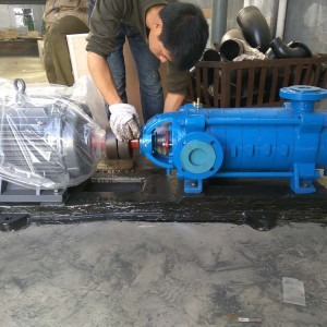
b. Multi-stage pump: that is, there are two or more impellers on the pump shaft. At this time, the total head of the pump is the sum of the heads produced by n impellers.
2) Classified according to work pressure
a. Low pressure pump: the pressure is lower than 100 meters of water column;
b. Medium pressure pump: The pressure is between 100 and 650 meters of water column;
c. High-pressure pump: The pressure is higher than 650 meters of water column.
3) Classification according to the way of impeller water inlet
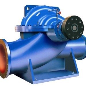
a.Single-side water inlet pump: also called single-suction pump, that is, there is only one water inlet on the impeller
b. Double-side water inlet pump: also called double-suction pump, that is, there is a water inlet on both sides of the impeller. Its flow rate is twice that of a single-suction pump, which can be roughly regarded as two single-suction pump impellers placed back to back together
4), according to the type of joint joints of the pump casing to classify
a. Horizontal split pump: that is, a joint seam is opened on the horizontal plane passing through the axis line.
b. Vertical joint surface pump: the joint surface is perpendicular to the axis line.
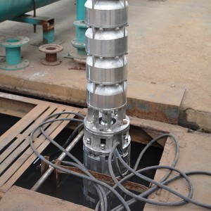
5) Classification according to the position of the pump shaft
a. Horizontal pump: the pump shaft is in a horizontal position
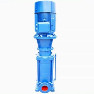
b. Vertical pump: the pump shaft is in the vertical position
6) Classification according to the way the water from the impeller is led to the press-out chamber
a. Volute pump: After the water comes out of the impeller, it directly enters the pump casing with a spiral shape
b. Guide vane pump: After the water comes out of the impeller, it enters the guide vane set outside it, and then enters the next stage or flows into the outlet pipe
We usually say that a certain water pump is a multi-stage pump, which refers to the number of impellers.
According to other structural characteristics, it may be a horizontal pump, a vertical combined surface pump, a guide vane pump, a high pressure pump, a single-side water inlet pump, etc. Therefore, it is called differently according to different. In addition, it can also be classified according to the purpose, such as oil pumps, water pumps, condensate pumps, ash discharge pumps, circulating water pumps, etc.
Post time: 2021-11-30